where E - Young modulus, I - diametral inertia moment of the shaft section, kinit mh – coefficient of moment stiffness of an equivalent link corresponding to fully open crack.
The equation has two summands – flexibility related to crack and flexibility of the beam without crack. It should be noted that irrespective of the beam shape, boundary conditions and the crack position, its contribution to general beam flexibility depends only on the coefficient kinit mh ,i.e. the first summand. While the beam is rotating, flexibility in the crack section changes. We obtain the following:

where go= - flexibility of the beam without crack, (q) kmh - current coefficient of moment stiffness for the given q .
Integrating two equations (5) and (7), we obtain:

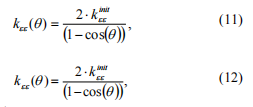
where taking the equation (6) into account we obtain the law of change in moment stiffness depending on difference in phases q :

The obtained moment stiffness of an equivalent link depends only on the shaft diameter, material characteristics and the crack depth. Change in crack position in the shaft, characteristics of the shaft including the support units does not change moment stiffness of an equivalent link (on condition that the section with crack remains the same in any part of the section with crack for which it was
obtained).
Going back to stiffness matrix obtained before, its stiffness coefficients may be written as the following:

where k initee , kinithh -initial values of moment stiffness at the corresponding axes for the fully open crack.
The task of kinitee , kinithh calculation may be solved in two ways. The first one is calculation of moment stiffness in FEM program. The second one is to use the theory of fracture mechanics. It gives an opportunity to calculate values of coefficients of local flexibility of open crack if its geometry, the shaft diameter and material characteristics are known [7,10].
Algorithm to simulate rotor system with crack
The following steps should be passed to obtain coefficients of moment stiffness of the crack.
1. The complete rotor model is created in one of the specialized programs to analyze rotor dynamics (for
example, in Dynamics R4).
2. The rotor section with crack is highlighted.
3. Crack divides the shaft section into two subsystems. Link described by the matrix of variable
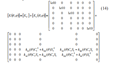
stiffness coefficients [K(q,j)] by dimension 6x6 is placed between subsystems.
4. Initial coefficients of moment stiffness kinitee , kinithh for open crack are obtained by the methods given
above. These data are initial for calculation.
Stiffness matrix coefficients of the link simulating crack are calculated while integrating of motion equations
of the rotor system for every q . At nonlinear statement matrix equation describing the nonlinear dynamic model
of the rotor system is the following:

where [M ] – matrix of inertia coefficients; [C] – matrix of damping and gyroscopes coefficients; [K] - matrix of stiffness coefficients; { u&&} ,{ u&} ,{u} – columns of vibrational accelerations, vibrational speeds and vibrational displacements correspondingly; {F(t)} - any types of dynamic loads– internal and external.
Stiffness matrix of an equivalent link may be divided into two parts: constant and variable, and the following is true:

[KC ] is included into the general stiffness matrix of the [K] system. Matrix ( ) [ q j ] n , K is used to calculate reactions of a nonlinear link:

where urx , ury – mutual rotations of the sections around the corresponding axes.
The final motion equation of the system is the following:

The given equation may be solved by numerical methods such as Runge-Kutta method, Newmark method, etc.
Adequacy of the suggested algorithm is done by comparison of flexibility of the two-support beam with
crack obtained in the finite-element system and according to the supposed algorithm in Dynamics R4. The task is to calculate the beam deflection under unit force in the crack sections for different phases between crack and force.
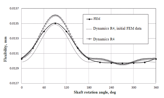
Figure 3 shows the results of check of the suggested algorithm. Three results are compared:
- flexibility is calculated using the finite element method (FEM). Radial flexibility of the model of the beam with crack is calculated in the FEM-system for the whole range of angular positions of crack;
- flexibility is calculated using Dynamics R4, initial data are obtained using FEM. Initial values of moment
stiffness for the fully open crack kinitee , kinithh are obtained solving equation (7) for kinitmh , and radial flexibility of the beam with crack gc at the corresponding direction is calculated using FEM. Moment stiffness for the intermediate angular crack positions changes from minimum to maximum according to the (10) law;
- flexibility is calculated using Dynamics R4. Initial data of moment flexibility for fully open crack kee init , khh init are obtained analytically using the algorithms of fracture mechanics [7, 10]. Value of moment flexibility for intermediate angular crack positions changes from minimum to maximum according to the law (10).

Figure 3 Change in beam flexibility in crack sectionper a revolution
The results in calculation of FEM-model and models in Dynamics R4 are close. Calculation results with initial conditions obtained analytically differ from the FEM results less than 1%. At the same time, initial stiffness is calculated analytically much faster than FEM calculation and requires less working hours and so easier-to-use.
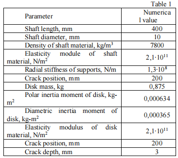
Geometry and parameters of rotor with crack
Geometry of the rotor with crack is chosen to show the algorithm work to the best advantage, Table 1. The rotor with the central disc, the supports are placed at the shaft ends.


