Introduction
The important direction in vibration diagnostics of aviation gas turbine engines and turbomachines is diagnostics through modelling. Modelling gives an opportunity to link the presence of some kinds of machine defects with signs of its presence in the vibration signal. One of such defects is crack appearance in the shafts of aviation engines and turbomachines which is unallowable. So the most important task of the diagnostic system is to detect crack in time and forecast its progress.
Appearance of crack in the rotor results in local stiffness decrease. Value of stiffness loss depends on geometric characteristics of crack. If static load such as weight force is applied, crack opens and closes while the rotor is rotating. As a result, the shaft stiffness changes per a cycle. Crack in the rotor system leads to the following changes in vibrational signal [1]:
· increase in amplitude of 1x harmonic of rotating speed due to growth of static deflection caused by stiffness decrease.
· appearance of 2x component of rotating speed due to asymmetric rotor stiffness.
· appearance of 3х component of rotating speed due to cyclical opening and closing of crack.
The main task of the mathematical model is description of value and law of local change in stiffness in
the place where crack takes place considering as many factors as possible.
There are several approaches to simulate crack. In the simplest cases crack is simulated by decrease in radial stiffness of the whole shaft [2,3,4]. In the other cases the shaft part, where crack takes place, is replaced by an equivalent beam element. Coefficients of stiffness matrix of such element are calculated taking crack into account and change per a cycle. In work [5] calculation of stiffness matrix of the beam element with crack is based on use of inertia moments of the beam section considering crack. In work [6] stiffness matrix of such element is calculated on the basis of equations of mechanics of solid bodies’ destruction. Crack may be simulated by elastic link connecting boundary sections of the shaft in the place of its location and giving the crack moment stiffness [7,8].
Change in crack stiffness depending on its opening and closing while the rotor is rotating may be described mathematically in different ways. In the simplest case it may be assumed that crack has only two positions: entirely opened or completely closed, and step function may be applied to describe its stiffness change mathematically [4].
Work [3] describes the most spread models of stiffness change. One of them is Gasch equation. Change
in stiffness takes place depending on the angle between phase of static force and crack phase and described by 17 harmonics of Fourier series. The same article gives Maes & Davies equation where stiffness changes depending on angle according to cosine law. In the Yang model stiffness changes by the cosine law in degree of relative crack depth.
This article develops the crack model on the basis of existed approaches and also presents the methodology that gives opportunity to highlight signs used to detect its condition for the exact rotor.
The algorithm is included into the Dynamics R4 software program [9], which represents the dedicated
system on calculation of dynamic behavior of complex rotor systems.
Crack model
Within the accepted simulation conception, crack in the shaft model is replaced by an elastic link dividing the shaft into two sections and describing by stiffness matrix with variable coefficients. If there is no crack, strain compatibility condition between the sections of the shaft parts is accomplished, so all the mutual displacements are prohibited. We introduce the rotating coordinate system ηOε lying in the crack area, Figure 1. Its origin coincides with the origin of the fixed coordinate system XYZ. The shaft executes two motions – proper rotation and precession around Z axis. When describing crack we consider only rotation around η and ε axes. Displacements at other freedom degrees are neglected.
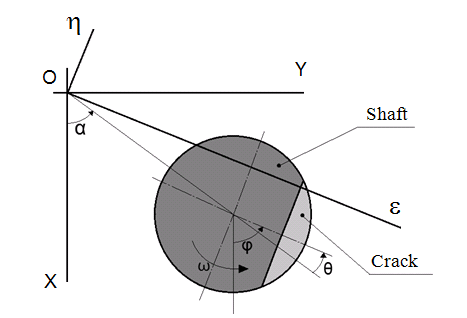
Figure 1. Crack section
Flexibility matrix of the link simulating crack in the rotating coordinate system may be written as the following:
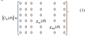
where q = j -a - difference in phases, j - shaft rotation angle, a - precession angle; gee (q) and ghh (q ) - variable coefficients of moment flexibility.
Flexibility depends on angle q because while the shaft is rotating, crack opens and closes. Stiffness matrix is obtained by inversion of the [GR (q)] matrix, and zero flexibility coefficients at the main diagonal lead to obtainment of stiffness coefficients going to infinity. We limit value of such stiffness coefficients by 1е10 N/m; this assumption does not affect significantly the result, i.e. we obtain
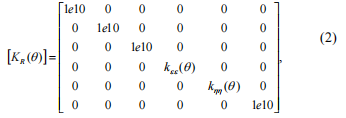
Stiffness matrix is transformed into the fixed coordinate system using the following equation:

where [T]- rotation matrix (4), where C1 = cos(j), S1 = sin(j).
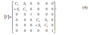
Multiplying matrixes in correspondence with the equation (3) we obtain:

We carry out some transformations that give opportunity to pass to the simpler description of the crack stiffness matrix and the algorithm of its coefficients obtainment. In correspondence with the Maes model, it may be assumed that radial flexibility of the circular beam with crack changes from minimum to maximum value by cosine law.

where g0 - flexibility of the beam without crack (minimum value), gc - flexibility of the beam with open crack (maximum value).
We replace crack by a hinge with moment stiffness kinit mh . The beam boundary conditions should provide its statical definability as it shown in Figure 2.
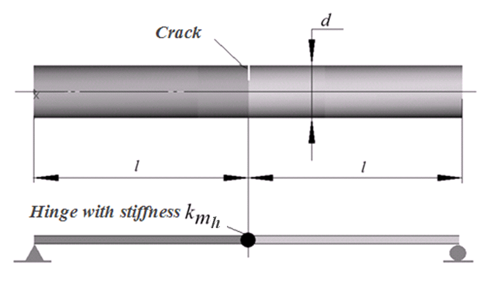
Figure 2. Replacement of crack by hinge
Then radial flexibility of highlighted section of the shaft with open crack is obtained as:

where E - Young modulus, I - diametral inertia moment of the shaft section, kinit mh – coefficient of moment stiffness of an equivalent link corresponding to fully open crack.

